Kopfring
Kopfrings (nose rings) were triangular or L-shaped steel rings. They were sometimes welded around the nose of SC type bombs to reduce excessive penetration again land targets and prevent bombs skipping across the water surface against naval targets.
These rings may also be found on on the SD 70 and SD 1700 bombs.
Source: TM 9-1985 2, German Explosive Ordnance (1953)


Source:
TM 9-1985 2, German Explosive Ordnance (1953)
Anti ricochet plates
Much like the kopfring, the anti ricochet plates were attached to bombs to reduce ricocheting, but it’s construction is entirely different, consisting of a plate attached to the suspension bolt socket.
The Type I was only used on the SC 250 and was constructed of a conical cup with a dished plate welded to it.
The conical cup is made from 5mm steel and is designed to sheath over the nose of the bomb. The 25 cm diameter plate is welded to the cup and is supported by eight 5mm stiffening ribs. The entire constructing is attached to the nose of the bomb with a bolt to the suspension socket at the nose of the bomb.
The Type II was used for SC 50 bombs. A cylinder, 15 mm in diameter and 2.4 cm thick is machined to fit over the nose of the bomb. A circular cup of 86 mm diameter with a hole in the centre is is welded to this cylinder. The construction is attached to the nose of the bomb with a bolt to the suspension socket at the nose of the bomb.
Stabo
Source: Tactical and Technical Trends No. 23 (1943)
A stabo bomb, short for Stachelbombe, “spike bomb”, were the name for bombs with an spike on the nose. They were quite rare and not used much. Contrary to common misconception, these spikes were not for piercing armour, nor were they used to detonate the bomb above ground like the daily cutter fuse or Dinort rod.
They were instead used in precision bombing runs. Due to the danger close nature of these attacks, bombs could only be used with delayed fuses such as timed or disturbance fuses. This to prevent the attacking aircraft from being caught in the blast zone, or to create a mine, blowing up a vehicle as well as the embankment. To prevent the bomb from bouncing or sliding away between impact and detonation, the Stabo could be attached to literally pin the bomb into the ground.
They were mostly used against railway lines and similar infrastructure were precision bombing was required.
Unlike most other modification these spikes were not connected to the front suspension socket in the bomb. Instead these bombs were specially manufactured with a threaded lug at the nose, on which the Stabo could be attached. These bombs were generally held to high quality standards.
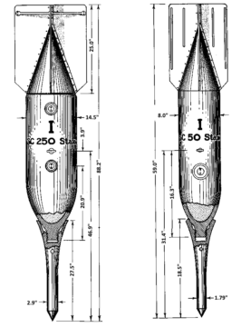
| SC 50 stabo | SD 70 stabo | SC 250 stabo | SC 500 stabo | |
|---|---|---|---|---|
| Total weight | 61.8 Kg | 71.8 Kg | 281.4 kg | 305 kg |
| Length | 47.75 cm | 47.75 cm | 57.9 cm | 61 cm |
| Diameter | 4.5 cm | 4.5 cm | 7.5 cm | 7.5 |
| Marking on Tail | Yellow | Red | Yellow |
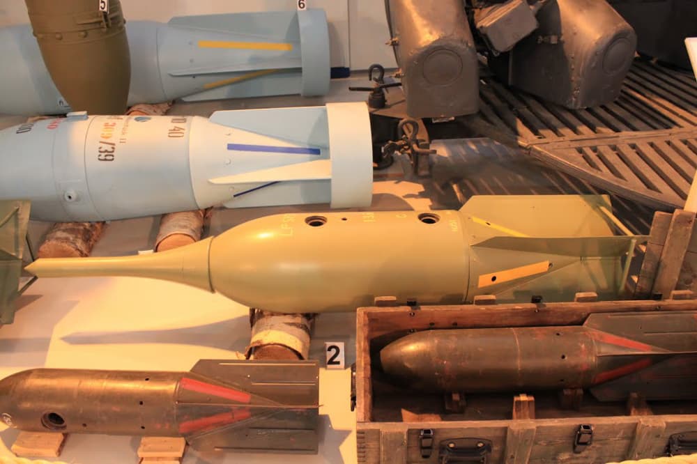
SC 250 Stabo at the Finnish Air Force Museum 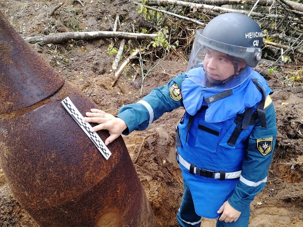
Unexploded SC-250 bomb with stabo spike found near a railway near Antsiferovo, Russia 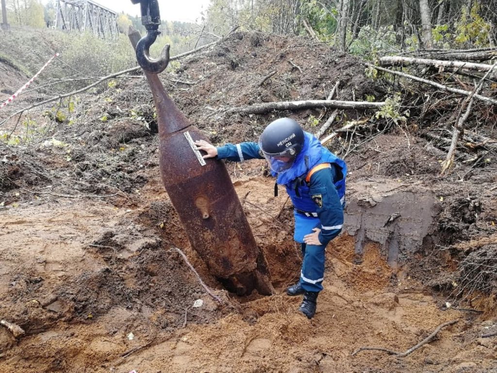
Dinort Rod
Source: TM 9-1985 2, German Explosive Ordnance (1953)
Dinort rods, or “Dinortstabe” are rods secured to the top of high explosive type bombs to make them detonate before burying into the ground, increasing their effect, similar to the American “Daisy cutter” fuse.
The rods are named after Oskar Dinort, a German ground attack aircraft pilot during WW2. During his campaign in Greece around 1941, he believed the effect of their bombs used against Greek troops was greatly reduced due to the bomb penetrating the ground before exploding. His solution was to fit a rod at the nose of the bomb, causing the bombs to detonate about 30 cm above ground, increasing their effect.
Bombs equipped with Dinort rods could be horizontally attached to aircraft, and were mosty used by the following planes:
- Junkers Ju 87
- Messerschmitt Bf 109/110
- Heinkel He 111 H-11
- Dornier Do 217
A minimum drop distance of 400 meter was recommended for the SD50/70 to prevent damaging the plane with the shock wave.
While the Dinort Rod was believed to be developed during Oscar Dinort’s Creta campaign in 1941 [1], The first published American account of at least a similar construction was not until April 22 1943. An article in Tactical and Technical Trends No. 23 Describes a ballistic cone labelled “ZAR 50”:
While the German air plane bomb usually detonates below the ground level forming a crater, and permitting persons in the vicinity to get some protection by lying down, a new type of bomb with an extension rod screwed into the nose to give a “daisy-cutter” air-burst has been discovered in Libya. Against such a bomb, both vertical and horizontal cover is needed. There is evidence that similar rods are used in the 250-kilogram (550-lb), 500-kilogram (1,100-lb), and 1,000-kilogram (2,200-lb) bombs in attacks on buildings and small craft.
Tactical and Technical Trends No. 23, April 22, 1943
The rod adapted to a 250-kilogram bomb, shown in the accompanying sketch, lacked a cardboard ballistic cone, but there is no doubt that one was fitted to it. From Malta have come reports of “dumbbell bombs,” and probably bombs fitted with these rods would have such an appearance when viewed from the ground while falling, particularly if they wobbled a bit.
The first account of Dinort rod itself doesn’t appear until December that year in issue 41 of Tactical and Technical trends, which describes the Din st 250
Many earlier specimens of German bomb nose-rods (see Tactical and Technical Trends No. 23, p. 24) have been buckled when recovered, presumably because the angle of impact of the bomb was too oblique. It is assumed that the nose rods now described are intended, by virtue of the solidity of their construction and the means taken to increase the mutual rigidity of bomb and nose rod, to ensure satisfactory operation for low-level attacks.
The Dinort nose-rod consists of a cast steel cup and plate, welded one at each end of a drawn steel tube as shown in the sketch. Within the cup is welded a central threaded boss which screws into the nose suspension lug recess of an SD 250 (thick-walled, HE bomb, 550 lb (249 kg)˜ ) in which position the flange of the cup will embrace the nose of the bomb providing considerable lateral rigidity. The details of the rod follow:
Diameter of plate – 9.45 in (24 cm)˜
Thickness of plate – 0.20 in (5 mm)˜
Diameter of cup – 5.55 in (14 cm)˜
Thickness of cup – 0.30 in (7,6 mm)˜
Length of rod – 14.80 in (38 cm)˜
Diameter of rod – 2.75 in (7 cm)˜The whole device is painted buff and the marking Din St 250 is stencilled in white paint on the side of the plate remote from the bomb.
Tactical and Technical Trends No. 41, December 30, 1943
Source:
[1] Hitler’s Stuka Squadrons: The JU 87 at War 1936-1945, John Ward
Source: http://www.luftarchiv.de/
construction of the Dinort rod
The Dinort rod may be made out of wood or metal, the metal variant consisting of a drawn steel tube with a circular steel plate welded to the base and a steel cup welded to the top. A threaded lug is also welded to the top and passes trough a hole in the cup. This lug can be screwed into the suspension bolt socked at the nose of a bomb to attach the Dinort rod. The flange of the cup will
The wooden variant consists of a square wooden stick with two square wooden plates nailed to the bottom, and two U shaped steel plates welded together are secured with screws at the top. A bolt is welded onto the U shaped steel plates to secure the rod to the bomb. The construction was painted in buff, and the name was stencilled to the side of the baseplate with white paint.[1]
The wooden variant consists of a square wooden stick with two square wooden plates nailed to the bottom, and two U shaped steel plates welded together at the top. a bolt is welded onto the U shaped steel plates to secure the rod to the bomb.
Source:
TM 9-1985 2, German Explosive Ordnance (1953)
[1] Tactical and Technical Trends No. 41 (1943)
| DIN st 50/DIN st 70 | DIN st 250 | DIN st 50/70 | ||
|---|---|---|---|---|
| usage | SD50/SD70 | SD250 | SD500 | SD50/70 |
| material | Steel | Steel | Steel | wood |
| length | 60 cm | 37.5 cm | 37.5 cm | 57.5 cm |
| rod diameter | 5.5 cm | 7 cm | 7 cm | 5.7 cm square |
| cup diameter | 14 cm | |||
| base plate diamter | 12 cm | 24 cm | 32 cm | 10 cm small 10.8 cm large |
| weight | 2.4 kg |
Source: “Stuka”, Gebhard Aders, Werner Held, 1989
Jericho-Gerät
As a form of physiological warfare, small whistles called Jericho Devices or Jericho whistles could be attached to the tail of SC/SD 50 and SC 250 Bombs. These would produce the loud, characteristic bomb whistle noise when falling to reduce morale. Similar to the well know “Jericho Trumpets”, the sirens attached to the landing gear of the Stuka.
There whistles were attached in pairs of 4 on the tail of the bomb, opposite of each other.
A pamphlet, “Civil Defence Training Pamphlet No 2: Objects Dropped From The Air”, Issued by the British Ministry of Home Security in 1944, describes two types of flutes; One is described as a “black cardboard tube, shaped like an organ pipe”, and the other as “an adapted bayonet scabbard, with an attachment for fastening it to one of the vanes of the bomb.”
8. WHISTLE ATTACHMENT FOR SCREAMING BOMBS
Civil Defence Training Pamphlet No 2: Objects Dropped From The Air, Ministry of Home Security, 1944
Two types of whistle, sometimes attached to the vanes of German high explosive bombs, causing them to scream as they fall, are illustrated in Figure 35. These whistles are often found near the scene of a bomb explosion.
One type is a black cardboard tube, shaped like an organ pipe. The other model is an adapted bayonet scabbard, with an attachment for fastening it to one of the vanes of the bomb. Both models are approximately 14 in. in length and 1 1/2 in. in diameter, the vent being about 4 in. from the closed end, which is rounded. Owing to the mechanical weakness, the former often breaks in two at the vent and the parts may be found separately.
In the second type, the body of the pipe is sometimes a hollow sheet-metal tube, spot welded in two seams down the side, with a wooden nose secured to the tongue of the metal tube by two nails.
(Note: 1-kg. incendiary bombs have also been found fixed to the vanes of a 50-kg. H.E. bomb by clips.)

Civil Defence Training Pamphlet No 2: Objects Dropped From The Air 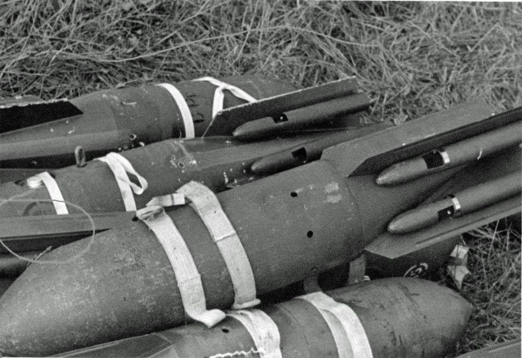
SD-50 bombs with Jericho Gërat whistles attached
Source
Air Force Technical Order TO 39B-1A-9 German Exlplosive ordanance (march 1953)
TM 9-1985 2, German Explosive Ordnance (1953)
Tactical and Technical Trends No. 23 (1943)
Tactical and Technical Trends No. 41 (1943)
Stuka, Gebhard Aders, Werner Held (1989)
Hitler’s Stuka Squadrons: The JU 87 at War 1936-1945, John Ward (2003