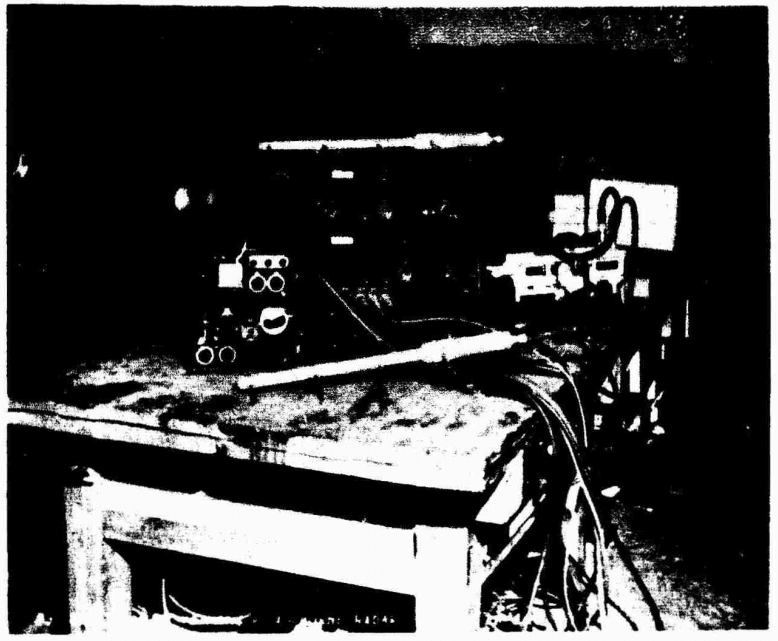
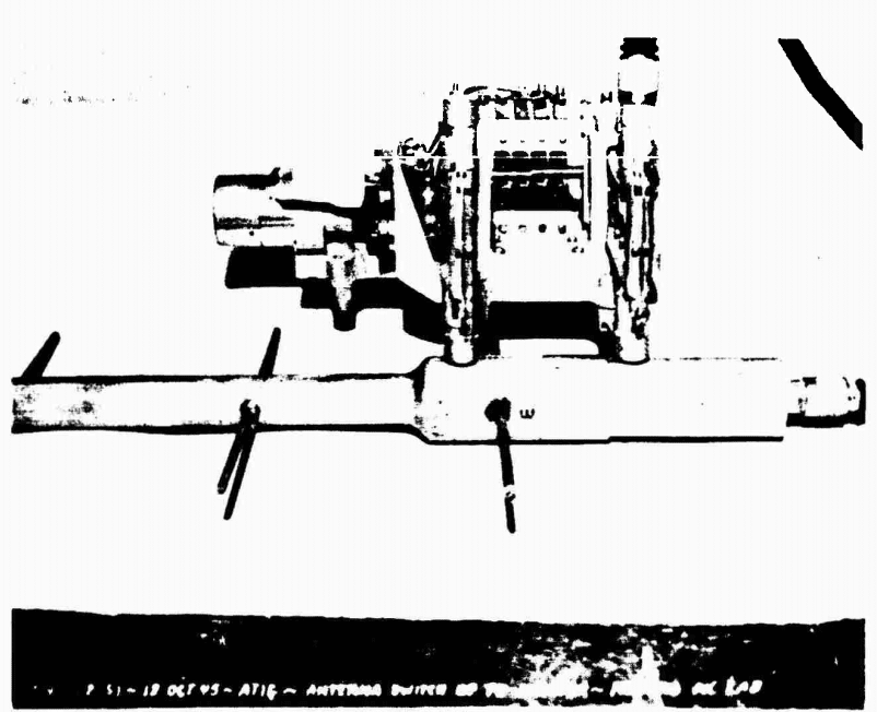
十八試空二号無線電信機 (18-shiki Ku-2 Gō musen denshinki , Prototype 18 Ku 2 Wireless Telegraph) was a search radar for night fighters, developed by the 2nd Naval Technical Institute and produced by Toshiba
When night bombardments by the Americans started, the need for a radar for finding the bombers became clear. The Japanese already had a working radar set with the H-6, however this was a long range detection radar, unsuitable for actually locating the bomber formations.
As a response the FD-2 was developed from the earlier failed FD-1 airborne detection radar. About 100 units were produced and installed on Nakajima J1N1 and Yokosuka P1Y aircraft of the 302 Kokutai.
The performance however was underwhelming, with an insufficient range of only 3 km. Increased drag due to the antennae and countermeasures deployed by B-29 further decreased the effectiveness. This later resulted in the electronics being removed from most aircraft with only the antenna array remaining.
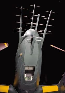
Source: Smithsonian
Functioning
The FD-2 uses four fourward facing Yagi style antenna with five elements (the sideway facing rods). Two pairs, each with a sending (top and bot) and a receiving antenna (left and right). The set uses horizontal lobe switching to find the target. Here the two sets would be pointed slightly off to the side of the plane. An electrical switch would continuously switch between the sets. The signal strengths would then be compared to determine the range and azimuth of the target. This would then be shown on a CRT display.
Surviving examples
After the War, American forces captured four Nakajima J1N Gecko’s. One of these machines was restored and is on display at the Steven F. Udvar-Hazy Center. This machine is equipped with the antenna array of an FD-2 radar, however the radar electronics were not present on the aircraft.
After the war, the Americans captured an working example of the FD-2 radar as well at Meguro Park Laboratory, Tokyo. It was send back to the U.S. for testing, but it’s current day status or whereabouts are unknown.
Technical Specifications
| 十八試空二号無線電信機 / Prototype 18 Ku 2 Wireless Telegraph |
||||
|---|---|---|---|---|
| Designation | FD-2 | |||
| Object | Night fighter interception radar | |||
| Research | started | End 1938 | ||
| Finished | Augustus 1944 | |||
| Operational status | Cancelled | |||
| Installation | Transmitter in nose, indicator at observer’s seat | |||
| Frequency | 0.6 meter / 500 kHz | |||
| Power Output (Peak) | 2.5 kw | |||
| Pulse Length | 3 µs | |||
| Repetition Frequency | 1000 c/s | |||
| Weight | 70 kg | |||
| Units build | ~100 | |||
| Transmitter | Oscillation Circuit | Modulated Oscillator | ||
| Oscillator Valve | T-321 x1 | |||
| Receiver | Intermed. Freq. | 10 mc | ||
| Detector | 1st 2400 | 2nd FM-2A05A | ||
| Local ocillator | UN-955 | |||
| Scope Representation |
Diameter | 75 mm | ||
| Scanning Axis | Sinusoidal | |||
| Scale | None | |||
| Antenna | Type | 4 Yagi antenna | ||
| Gain | 8db | |||
| Beam Angle | Horiz. | θƒ = ~30° | ||
| Vertical | θƒ = ~30° | |||
| Max. Range (Max.Effective Scale) | 75 (theoretical) 3 against aircraft |
|||
| Minimum Distance | 600 meter | |||
| Accuracy of Range | ≃± 5% | |||
| Distance Discrimination | ≃500 m | |||
| Accuracy of Bearing | ± 0.5° | |||
| Angle Discrimination | ≃ 60° | |||
| Operator | Pilot | |||
Reports of the U.S. Naval Technical Mission to Japan
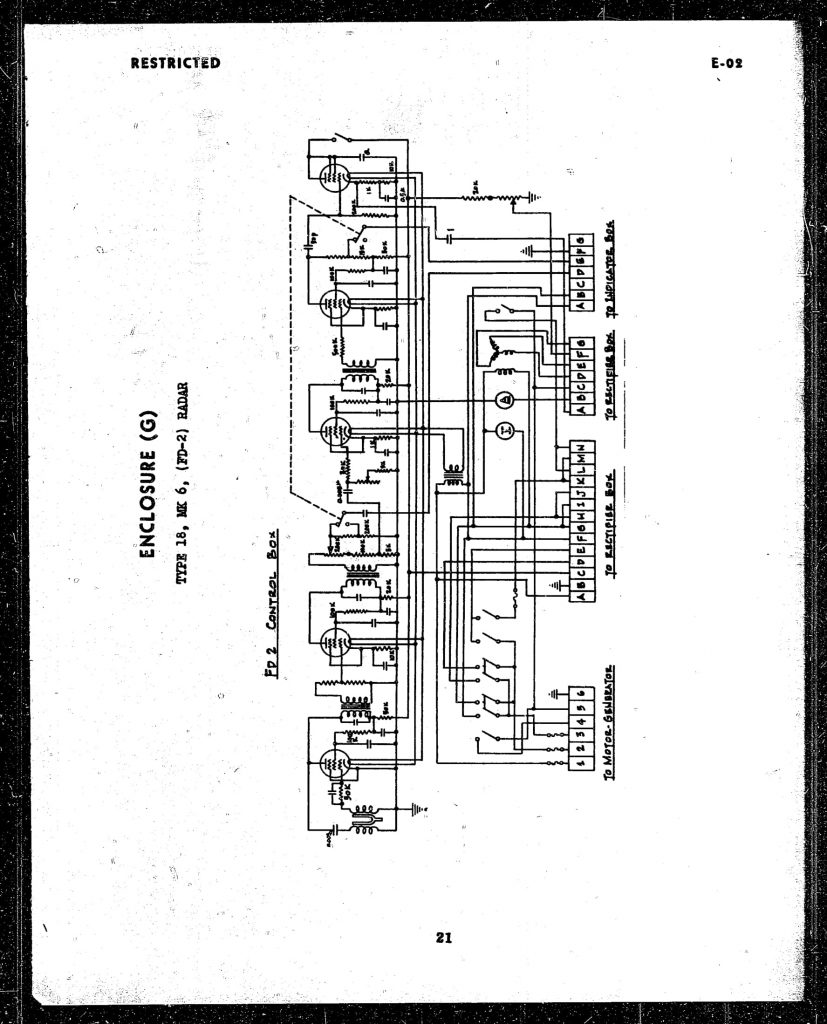
Control box 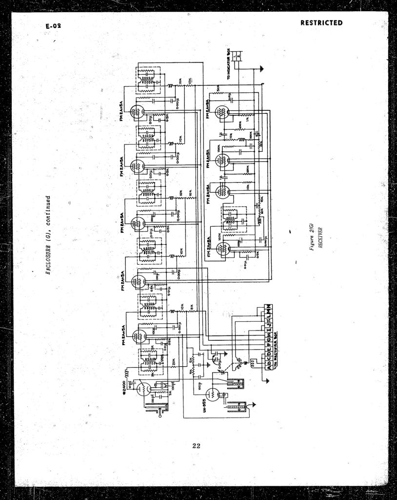
Receiver 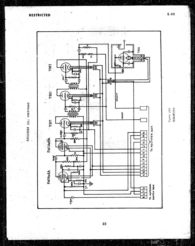
Transmitter 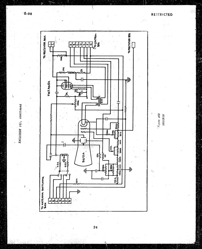
Indicator 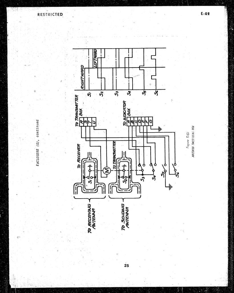
Antenna Switching box 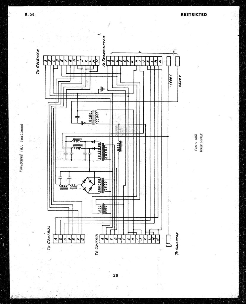
Power Supply 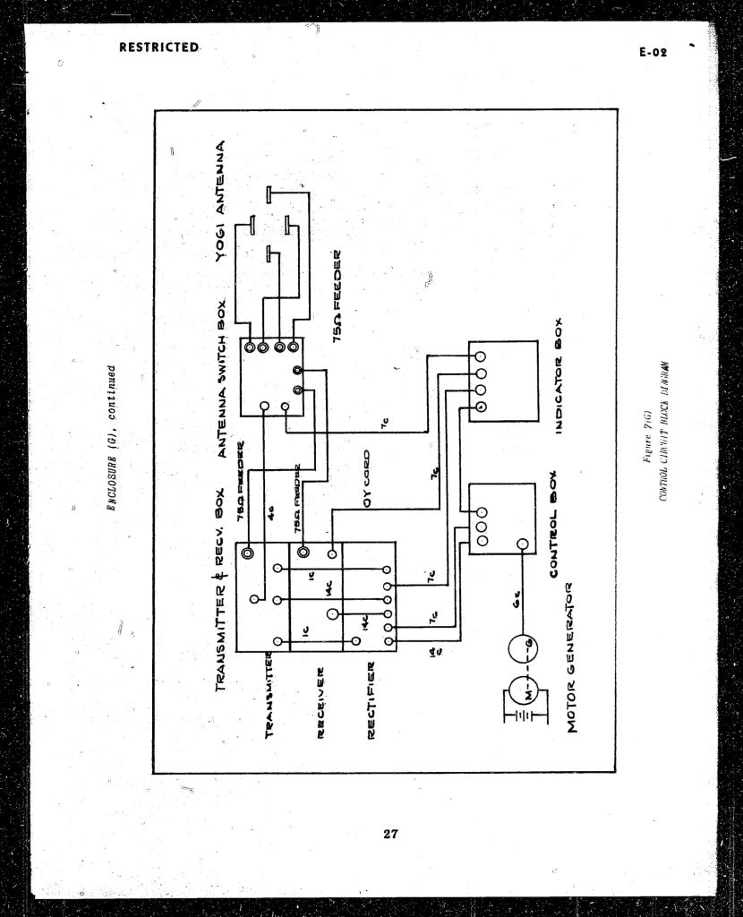
Control Circuit block Diagram 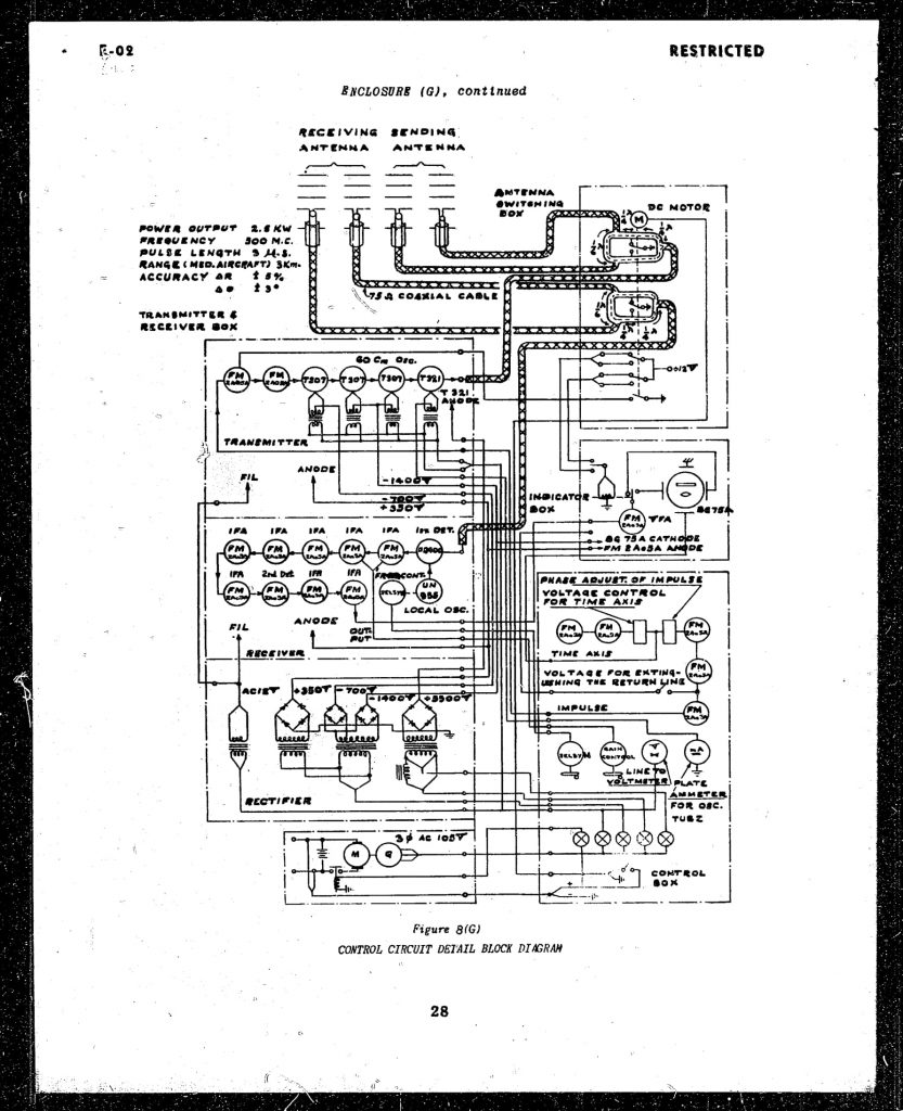
Control Circuit Detail Block Diagram
Sources
- A short survey of japanese radar Volume 1
- A short survey of japanese radar Volume 3
- Reports of the U.S. Naval Technical Mission to Japan, 1945-1946. Series E-02 Japanese Airborne Radar
- Famous Airplanes of The World 057- Nakajima J1N Gekko Type 11 (1996) / 『世界の傑作機No.57 海軍夜間戦闘機 月光』文林堂
